Development
- Angle table
- Inverse Kinematics
- Position Testing
There are currently few tasks at hand
- Make the Robot Walk
- Then add object avoidance
- Stream Video through webcam and identify persons.
The development have devided into 4 stages( #update ) for the timebeing
- [[#Development Phase 0]]
- [[#Development Phase 1]] -> making the robot walk
Development Phase 0
Prerequisites
Tasks
- Find initial positions of each servos
During the first step it is found that there is some offset about the pulse width. - Tweak the servos to get the desired angles .
- Integrate the whole part to the code
Intro
Threre are 17 servos in total , each servo can rotate from 0 to 180 degrees , it was not clear at first that the MG995 can rotate upto angle 180 or not. But later some source like this show that it is indeed possible to for the servo to rotate upto 180.
2 PCA9685 as Driver
#define SERVO_MIN  125
#define SERVO_MAX  625
This is the value of SERVOMIN and SERVOMAX found in the internet code , now we have to find the value corresponding to our servo.
We know the PCA9685 has a 12bit PWM
the MG995 has the following PWM feature

now the new code will become
#define SERVO_MIN  102
#define SERVO_MAX  512
#define SERVO_FREQ 50
#define SERVO_ANGLE_MIN 0
#define SERVO_ANGLE_MAX 180
Servoo
void setup() {
  board1.setPWMFreq(SERVO_FREQ);
}
uint16_t get_pulse(uint8_t _angle){
 return map(_angle,SERVO_ANGLE_MIN, SERVO_ANGLE_MAX, SERVO_MIN,SERVO_MAX);
  }
Usage
#define I2C_ADDR 0x40
Adafruit_PWMServoDriver the_servo = Adafruit_PWMServoDriver(I2C_ADDR);
 #define /* let*/ first_pin /* of pca9685 */ = 0 ;

for(uint8_t angle = 0 ; angle < ANGLE_MAX ; angle++){
	the_servo.setPWM(first_pin , 0,get_pulse(angle));
}
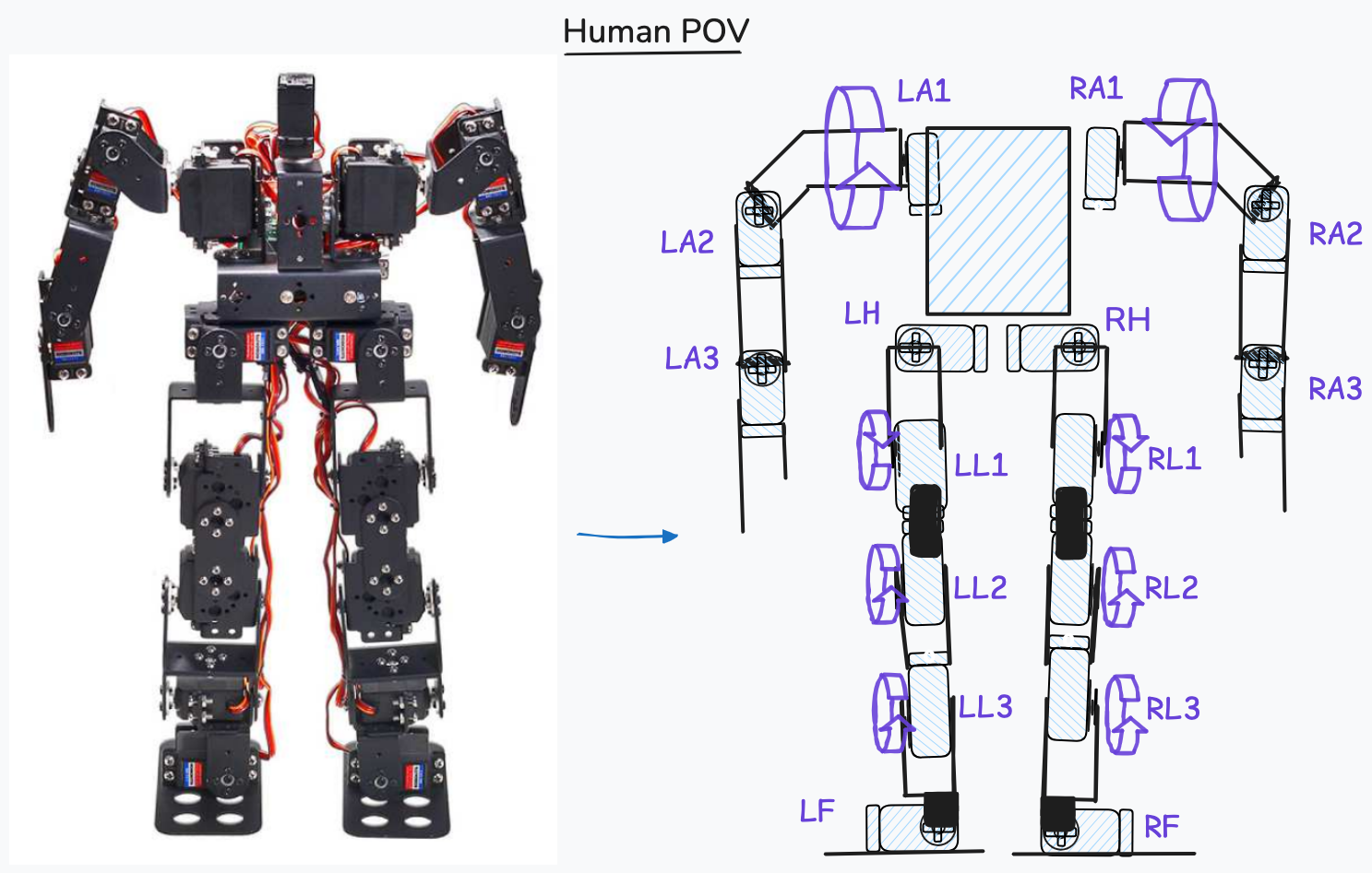
2.1 Pin Defenitions
The PCA9685 has 16 output pins, but the thing is our robot has 17 servos so im going to use additional PCA9685 or a dedicated pin(15) for the last servo(head )
| Pin Name | Unit | Value |
|---|---|---|
| PIN_LA1 | Left arm | 0 |
| PIN_LA2 | Left arm | 1 |
| PIN_LA3 | Left arm | 2 |
| PIN_RA1 | Right arm | 3 |
| PIN_RA2 | Right arm | 4 |
| PIN_RA3 | Right arm | 5 |
| PIN_LH | Left Hip | 6 |
| PIN_RH | Right Hip | 7 |
| PIN_LL1 | Left Leg | 8 |
| PIN_LL2 | Left Leg | 9 |
| PIN_LL3 | Left Leg | 10 |
| PIN_RL1 | Right Leg | 11 |
| PIN_RL2 | Right Leg | 12 |
| PIN_RL3 | Right Leg | 13 |
| PIN_LF | Left Foot | 14 |
| PIN_RF | Right Foot | 15 |
#define PIN_LA1 0
#define PIN_LA2 1
#define PIN_LA3 2
#define PIN_RA1 3
#define PIN_RA2 4
#define PIN_RA3 5
#define PIN_B1 6
#define PIN_B2 7
#define PIN_LL1 8
#define PIN_LL2 9
#define PIN_LL3 10
#define PIN_RL1 11
#define PIN_RL2 12
#define PIN_RL3 13
#define PIN_LF 14
#define PIN_RF 15
3 Finding the initial position of all servos
Initial position in the sense that the position of the servo when the robot is in the standing position
3.1 Initial Positions
// Servo Vals.h
#define SERVO_ANGLE_MIN 0
#define SERVO_ANGLE_MAX 5000
#define SERVO_MIN  102   // .5ms
#define SERVO_MAX  512   // 2.5ms
#define SERVO_FREQ 50
Tests
| File | ID | pin | Initial Angle | Status | Rotation |
|---|---|---|---|---|---|
| 03 Development |
|
|
|
|
|
pulse tester
import requests
url = "http://192.168.137.142/setServo"
def set_position(val,id=0):
	req_params= {
		"id": id,
		"position": val
		}
	response = requests.get(url, params=req_params)
	print(f"Response: {response.text}")
while True:
	val = int(input("Enter position"))
	set_position(val)

	if val == 0:
		break;
angle tester
import requests
url="http://192.168.248.254/setServo"
import time
def get_pulse(val):
	return val * (512 - 102 ) /180 + 102
def set_position(val,id=0):
	req_params= {
		"id": id,
		"angle": val
		}
	response = requests.get(url, params=req_params)
	print(f"Response: {response.text}")
while True:
	for i in range(0,180):
		new_val = get_pulse(i)
		set_position(new_val,id=1)
		time.sleep(.1)
	for i in range(180,1):
		new_val = get_pulse(i)
		set_position(new_val,id=1)
		time.sleep(.1)
while True:
	val = int(input("Enter position"))
	if val == 1000:
		break;
	new_val = get_pulse(val)
	set_position(new_val,id=1)
new_val = 180
set_position(new_val,id=0)
LL1=0
LL2=10
LL3=180-39
RL1=180
RL2=170
RL3=39
RF=99
LF=99
import time
set_position(get_pulse(LL1),id=8) # LL1
time.sleep(1)
set_position(get_pulse(LL2),id=9) # LL2
time.sleep(1)
set_position(get_pulse(LL3),id=10) # LL3
time.sleep(1)
set_position(get_pulse(RL1),id=11) # RL1
time.sleep(1)
set_position(get_pulse(RL2),id=12) # RL2
time.sleep(1)
set_position(get_pulse(RL3),id=13) # RL3
time.sleep(1)
set_position(get_pulse(LF),id=14) # LF
time.sleep(1)
set_position(get_pulse(RF),id=15) # RF
set_position(160,id=12) # RL2
ideal
id = 5
zero_degree = {
	"id": id,
	"position": 102
}
one80_degree = {
	"id": id,
	"position": 522
}
min
response = requests.get(url, params=zero_degree)
print(f"Response: {response.text}")
max
response = requests.get(url, params=one80_degree)
print(f"Response: {response.text}")
Upper Body
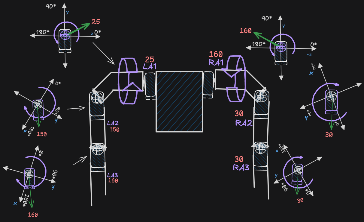
1. LA1
- [servo:: LA1]
- [pin:: 0]
- [initial_position:: 25]
- [status:: fine]
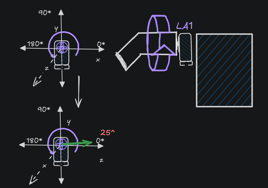
- Orientation X -> Z , Z -> -X
- Current [orientation::
]
- serv[rotation::
]
2. LA2
- [servo:: LA2]
- [pin:: 1]
- [initial_position:: 10]
- [status:: not fine]
3. LA3
- [servo:: LA3]
- [pin:: 2]
-
- [initial_position:: 160]
- [status:: fine]
4. RA1
- [pin:: 3]
- [servo:: RA1]
- [initial_position:: 160]
- The orientation of the servo is changed (z -> x and X -> -Z)
- [status:: fine]
- [rotation::
]
5. RA2
- [servo:: RA2]
- [pin:: 4]
- [initial_position:: 160]
- [status:: not fine]
- [rotation::
]
6. RA3
- [servo:: RA3]
- [pin:: 5]
- [initial_position:: 30]
- [status:: fine]
Lower Body
7. LH
- [servo:: LH]
- [pin:: 6]
- [initial_position:: 102]
- [status:: fine]
- [rotation::
] - Current [orientation::
]
8. RH
- [servo:: RH]
- [pin:: 7]
- [initial_position:: 102]
- [status:: fine]
- [rotation::
] - Current [orientation::
]
9. LL1
- [servo:: LL1]
- [pin:: 8]
- [initial_position:: 25]
- [status:: fine]
- [rotation::
] - Current [orientation::
]
10. LL2
- [servo:: LL2]
- [pin:: 9]
- [initial_position:: 25]
- [status:: fine]
- [rotation::
] - Current [orientation::
]
- First Initial position of Servo
- Rotate 90° Around the Y-Axis
(global axis)
According to
- 180° Around the X-Axis (Flips Y and Z Down) (global axis)
11. LL3
- [servo:: LL3]
- [pin:: 10]
- [initial_position:: 160]
- [status:: fine]
- [rotation::
] - current [orientation::
]
12. RL1
- [servo:: RL3]
- [pin:: 11]
- [initial_position:: 160]
- [status:: fine]
- [rotation::
]
13. RL2
- [pin:: 12]
- [servo:: RL2]
- [initial_position:: 165]
- [status:: fine]
- [rotation:: ]
4 Movements
Lets say we want to go from position a to b. the code will be like this
for (pos= _initial_position; ++pos; pos < _final_position){
            _servo_obj.setPWM(_this_servo_, 0, angleToPulse(pos));
            delay(DELAY_MS);
        }
- fist sets the position(
pos) os the starting position(_initial_position) - writes(
_servo_obj.setPWM(_this_servo , 0 , angleToPulse(pos)))- Calculates the current pulseWidth which is respected to the angle
- writes that to the servo.
- introduces some relay to make the movement smoother and reduces surge current
Here few things to consider
_final_positionis will be greater than_initial_position(_final_position > _initial_position)
4.1 Raising Hand
![[(output003)Model3ServoArm_trans_2.mp4]]
In this project , rasising hand is the simplest task, because it only involves moving only one servo LA1.
Now consider the following code again.
![[#^d90f88]]
This code is for [[#clock wise movement]] , in section [[#2 Finding the initial position of all servos]] and the table
![[#^b7c9fb]]
For the time beeing consider only LA1 , LA2 , LA3
| Servo | Unit | Position Degrees | 180 |
|---|---|---|---|
| LA1 | Left arm | 25 | to front |
| LA2 | Left arm | 0 | to up |
| LA3 | Left arm | 16 | to up |
4.1.1 Left Arm
import numpy as np
import matplotlib.pyplot as plt
arm_length = 1
angles_deg = np.linspace(0, 180, 180)
angles_rad = np.radians(angles_deg)
x = arm_length * np.cos(angles_rad)
y = arm_length * np.sin(angles_rad)
plt.figure(figsize=(6, 3))
plt.plot(x, y, label='Arm Tip Path', color='blue')
plt.plot([0, x[0]], [0, y[0]], 'r--', label='Start Position')
plt.plot([0, x[-1]], [0, y[-1]], 'g--', label='End Position')
plt.gca().set_aspect('equal')
plt.title('Servo Arm Sweep 0° to 180°')
plt.xlabel('X (cm)')
plt.ylabel('Y (cm)')
plt.legend()
plt.grid(True)
plt.show()
import numpy as np
import matplotlib.pyplot as plt

# Link lengths (both 1 cm)
L1 = 1.0
L2 = 1.0

# Generate angle combinations
theta1_deg = np.linspace(0, 180, 100)
theta2_deg = np.linspace(0, 180, 100)

theta1_rad = np.radians(theta1_deg)
theta2_rad = np.radians(theta2_deg)

# Meshgrid to compute all combinations of joint angles
T1, T2 = np.meshgrid(theta1_rad, theta2_rad)

# Forward kinematics for 2-link planar arm
# Base -> First Joint (L1) -> Second Joint (L2)
X = L1 * np.cos(T1) + L2 * np.cos(T1 + T2)
Y = L1 * np.sin(T1) + L2 * np.sin(T1 + T2)

# Plot
plt.figure(figsize=(6, 6))
plt.scatter(X, Y, s=1, c='blue')
plt.title("Reachable Workspace of 2-Link Arm")
plt.xlabel("X (cm)")
plt.ylabel("Y (cm)")
plt.axis('equal')
plt.grid(True)
plt.show()
5 Timeline
timeline
title AI Robot Development
May 1 : Initialization
	: Team forming
May 2 : Theoretical modeling
	: current servo position finding
May 7 : Lib Making
May 14 : Making it walk
May 20 : Implementing Emotes
May 30 : Expected to Finish Phase 1
6 References
- https://www.instructables.com/Making-humanoid-robot-from-Flated-water-pipe-and-s/
- https://projecthub.arduino.cc/ashraf_minhaj/mia-1-open-source-advanced-handmade-humanoid-robot-36429e
- https://github.com/AndreiBuzdugan/Little-Human-Robot/blob/main/Ultrasonic_Robot.ino
- https://github.com/hubonit/Humanoid-Robot-with-Arduino
- https://github.com/hubonit/Humanoid-Robot-with-Arduino/blob/master/GBotV3.ino
- https://github.com/gunarakulangunaretnam/mr-humanoid
- https://docs.manim.community/en/stable/
- https://gemini.google.com/app/2b0e2c2787d08884?hl=en-IN