Smart Watch Versions
red black grey oreng (orenge = +vcc black gnd) Aruncs31s@twilio
9V7MKPF5XPFUNELZP252J63L
Requirements
Working
The working prototype will send messages (current location) to specified number (parents,police and any another if any).
- The system also detects "HELP" command , ie. if someone says "HELP" from near the prototype the the system will triger the SOS message
Structure of SOS Message
https://www.google.com/maps?q=Lon,Lat
BILL Of Material
- VC-02 Ai Thinker Intelligent Offline Speech Recognition Module Purchase Link Datasheet
- Neo6M GPS Module Purchase Link DataSheet Tutorial [[#Neo 6m GPS]]
- SIM800L GPRS GSM Module Core Board Quad-band TTL Serial Port with the antenna Purchase Link
| Component | Cost |
|---|---|
| ESP8266 | 320 |
| GPS Module | 439.00 |
| Help recognittion Module | 1,099 |
| GSM Module | 410 |
| USB Charge converter | 10 |
| Battery & other | 200 |
| Total |
PINS
| D5 | Tx of GPS |
|---|---|
| D4 | Rx of GPS |
Version 1
Multi-column
Blank

SIM800L Interfacing
#define BAUD_RATE 9600
#define MIC_PIN A0

#if defined(ARDUINO)
#define GSM_TX 3
#define GSM_RX 2
#elif defined(ESP8266)
#define GSM_TX D5
#define GSM_RX D6
#endif
/* --- Config.h --- */
/* Source: https://lastminuteengineers.com/sim800l-gsm-module-arduino-tutorial/
 */

#include "Config.h"
#include <Arduino.h>
#include <SoftwareSerial.h>

// #if defined(ARDUINO)
SoftwareSerial gsmSerial(GSM_TX, GSM_RX); // 3 -> SIM800L Tx & 2 -> SIM800L Rx
// #elif defined(ESP8266)
// SoftwareSerial gsmSerial(D5, D6); // D5 -> SIM800L Tx & D6 -> SIM800L Rx
// #endif

void updateSerial() {
  delay(500);
  while (Serial.available()) {
    gsmSerial.write(
        Serial.read()); // Forward what Serial received to Software Serial Port
  }
  while (gsmSerial.available()) {
    Serial.write(
        gsmSerial
            .read()); // Forward what Software Serial received to Serial Port
  }
}
void setup() {
  Serial.begin(9600);

  // Start GSM Serial
  gsmSerial.begin(9600);

  Serial.println("Initializing...");
  delay(1000);

  gsmSerial.println(
      "AT"); // Once the handshake test is successful, it will back to OK
  updateSerial();

  gsmSerial.println("AT+CMGF=1"); // Configuring TEXT mode
  updateSerial();
  gsmSerial.println(
      "AT+CMGS=\"+917902504188\""); // change ZZ with country code and
                                    // xxxxxxxxxxx with phone number to sms
  updateSerial();
  gsmSerial.print(
      "Last Minute Engineers | lastminuteengineers.com"); // text content
  updateSerial();
  gsmSerial.write(26);
}

void loop() {
  updateSerial();
  delay(1000);
}
Neo 6m GPS
/*
 * Source:
 * https://randomnerdtutorials.com/esp8266-nodemcu-neo-6m-gps-module-arduino/
 */
#define BAUD_RATE 9600
#define MIC_PIN A0
#define GPS_BAUD_RATE 9600

#if defined(ARDUINO)
#define GSM_TX 3
#define GSM_RX 2
#elif defined(ESP8266)
#define GSM_TX D5 // This should connect to the TX pin of the GPS module
#define GSM_RX D6 // This should connect to the RX pin of the GPS module
#endif
/* --- Config.h ---*/
#include "Config.h"
#include <SoftwareSerial.h>
#include <TinyGPS++.h>

TinyGPSPlus gps;

// Create an instance of Software Serial
SoftwareSerial gpsSerial(GPS_RX, GPS_TX);

void setup() {
  // Serial Monitor
  Serial.begin(115200);

  // Start Serial 2 with the defined RX and TX pins and a baud rate of 9600
  gpsSerial.begin(GPS_BAUD_RATE);
  Serial.println("Software Serial started at 9600 baud rate");
}

void loop() {
  // This sketch displays information every time a new sentence is correctly
  // encoded.
  unsigned long start = millis();

  while (millis() - start < 1000) {
    while (gpsSerial.available() > 0) {
      gps.encode(gpsSerial.read());
    }
    if (gps.location.isUpdated()) {
      Serial.print("LAT: ");
      Serial.println(gps.location.lat(), 6);
      Serial.print("LONG: ");
      Serial.println(gps.location.lng(), 6);
      Serial.print("SPEED (km/h) = ");
      Serial.println(gps.speed.kmph());
      Serial.print("ALT (min)= ");
      Serial.println(gps.altitude.meters());
      Serial.print("HDOP = ");
      Serial.println(gps.hdop.value() / 100.0);
      Serial.print("Satellites = ");
      Serial.println(gps.satellites.value());
      Serial.print("Time in UTC: ");
      Serial.println(String(gps.date.year()) + "/" + String(gps.date.month()) +
                     "/" + String(gps.date.day()) + "," +
                     String(gps.time.hour()) + ":" + String(gps.time.minute()) +
                     ":" + String(gps.time.second()));
      Serial.println("");
    }
  }
}
      Serial.print("LAT: ");
      Serial.println(gps.location.lat(), 6);
      Serial.print("LONG: ");
      Serial.println(gps.location.lng(), 6);
#include <SoftwareSerial.h>
#include <TinyGPS++.h>
#define GPS_TX D6 // Connects to TX pin of GPS module
#define GPS_RX D7 // Connects to RX pin of GPS module
TinyGPSPlus gps;
SoftwareSerial gpsSerial(GPS_RX, GPS_TX);
void setup() {
	Serial.begin(9600);
	gpsSerial.begin(9600);
}
void loop() {
	unsigned long start = millis();
	while (millis() - start < 1000) {
		while (gpsSerial.available() > 0) {
			gps.encode(gpsSerial.read());
	}
	if (gps.location.isUpdated()) {
		Serial.print("LAT: ");
		Serial.println(gps.location.lat(), 6);
		Serial.print("LONG: ");
		Serial.println(gps.location.lng(), 6);
		Serial.print("SPEED (km/h): ");
		Serial.println(gps.speed.kmph());
		Serial.print("ALT (m): ");
		Serial.println(gps.altitude.meters());
		Serial.print("HDOP: ");
		Serial.println(gps.hdop.value() / 10.0);
		Serial.print("Satellites: ");
		Serial.println(gps.satellites.value());
	char buffer[30];
	sprintf(buffer, "%04d/%02d/%02d, %02d:%02d:%02d", gps.date.year(), gps.date.month(),gps.date.day(), gps.time.hour(), gps.time.minute(), gps.time.second());
	Serial.print("Time in UTC: ");
	Serial.println(buffer);
	Serial.println();
	}
  }
}
Speech Processing
Going to use raspberry pi for now
nmap 10.42.0.1-255
- ip address of pi
10.42.0.122 - username
multimediaextension<-- Shrink - passwd
2xsp<-- expand
MIC Interfacing
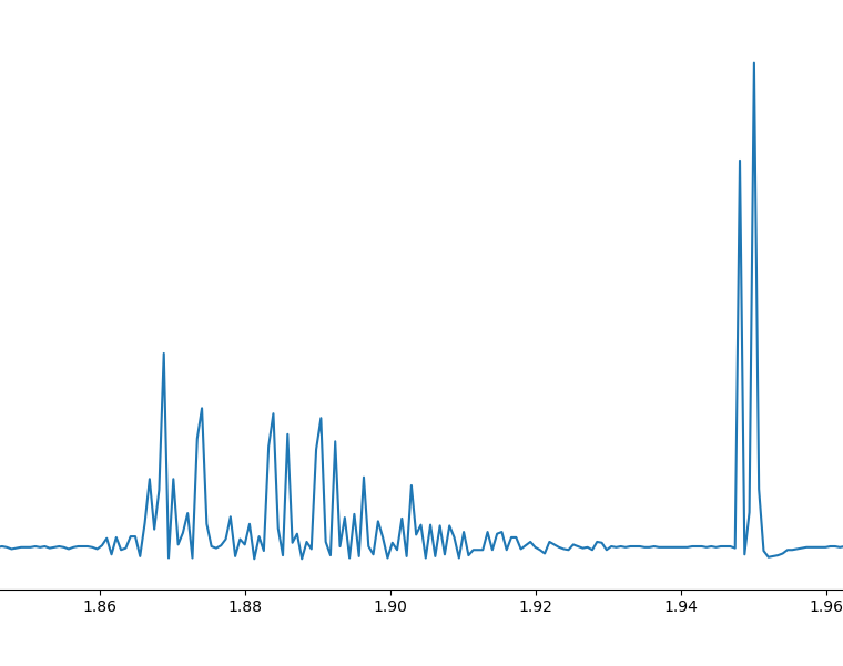
number of points/samples = 4581
starting of help
let this be
Ending of help
let this be
help took
- Picovoice Rhino Speech-to-Intent
Pyaudio Setup
# Debian
sudo apt-get install libasound-dev
# Fedora
sudo dnf install portaudio-devel
D1 Button Test
#include <Arduino.h>
void setup() {
  pinMode(D1, INPUT);
  Serial.begin(9600);
}
void loop() {
  Serial.println(digitalRead(D1));
  delay(500);
}
#include <Arduino.h>
void IRAM_ATTR theISR(){
	Serial.println("Button Pressed");
}
void setup(){
	Serial.begin(9600);
	attachInterrupt(D1,theISR,FALLING);
}
void loop(){
	delay(1000);
}
Help Test
#include <Arduino.h>
void IRAM_ATTR theISR(){
	Serial.println("Button Pressed");
}
void setup(){
	Serial.begin(9600);
	attachInterrupt(D8,theISR,RISING);
}
void loop(){
	delay(1000);
}
Sajesh Kumar Sir Suggestions
Version 2
Version 2 changes the design and includes a new lcd screen ,
Componnets
| Pins Used | Purpose |
|---|---|
| D8 | help Interrupt |
| D7 | Rx GSM |
| D6 | Tx GSM |
| D1 , D2 | I2C Lcd |
#include "ESP8266WiFi.h"
#include "NTPClient.h"
#include "WiFiUdp.h"
#include <Arduino.h>
#include <Config.hpp>
#include <LiquidCrystal_I2C.h>

// +5:30 hours for india
const long utcOffsetInSeconds = 19800;

char daysOfTheWeek[7][12] = {"Sunday",   "Monday", "Tuesday", "Wednesday",
                             "Thursday", "Friday", "Saturday"};

// Define NTP Client to get time
WiFiUDP ntpUDP;
NTPClient timeClient(ntpUDP, "pool.ntp.org", utcOffsetInSeconds);

LiquidCrystal_I2C lcd(0x27, 16, 2);

void setup() {
  Serial.begin(115200);
  WiFi.begin(SSID, PASSWORD);
  timeClient.begin();

  lcd.init();
  lcd.clear();
  lcd.backlight();

  lcd.setCursor(0, 0);
  lcd.print("Setting UP!");
  lcd.setCursor(0, 1);
  lcd.print("Please Wait...");
  while (WiFi.status() != WL_CONNECTED) {

    delay(500);
    Serial.print(".");
  }

  lcd.clear();
}

void loop() {

  timeClient.update();
  lcd.setCursor(0, 0); // Set cursor to character 0 on line 0
  lcd.print("Smart Watch");

  lcd.setCursor(0, 1); // Move cursor to character 0 on line 1

  lcd.print(daysOfTheWeek[timeClient.getDay()]);
  lcd.print(" ");
  lcd.print(timeClient.getHours());
  lcd.print(":");
  lcd.print(timeClient.getMinutes());
  lcd.print(":");
  lcd.print(timeClient.getSeconds());
  Serial.println(timeClient.getFormattedTime());
  delay(1000);
  lcd.clear();
}
12-02-25
#include <Arduino.h>
#define USE_ARDUINO_INTERRUPTS true    // Set-up low-level interrupts for most acurate BPM math
#include <PulseSensorPlayground.h>     // Includes the PulseSensorPlayground Library

const int PulseWire = A0;       // 'S' Signal pin connected to A0
const int LED13 = 13;          // The on-board Arduino LED
int Threshold = 550;           // Determine which Signal to "count as a beat" and which to ignore

PulseSensorPlayground pulseSensor;  // Creates an object

void setup() {
    Serial.begin(9600);

    // Configure the PulseSensor object, by assigning our variables to it
    pulseSensor.analogInput(PulseWire);
    pulseSensor.blinkOnPulse(LED13);       // Blink on-board LED with heartbeat
    pulseSensor.setThreshold(Threshold);

    // Double-check the "pulseSensor" object was created and began seeing a signal
    if (pulseSensor.begin()) {
        Serial.println("PulseSensor object created!");
    }
}

void loop() {
    int myBPM = pulseSensor.getBeatsPerMinute();      // Calculates BPM

    if (pulseSensor.sawStartOfBeat()) {               // Constantly test to see if a beat happened
        Serial.println("♥  A HeartBeat Happened ! "); // If true, print a message
        Serial.print("BPM: ");
        Serial.println(myBPM);                        // Print the BPM value
        }

    delay(20);
}
#define GSM_TX D3

#define GSM_RX D4

/* -- Config.h --- */


#include <Arduino.h>

#include <SoftwareSerial.h>


SoftwareSerial gsmSerial(GSM_TX, GSM_RX); // 3 -> SIM800L Tx & 2 -> SIM800L Rx


void updateSerial() {

delay(500);

while (Serial.available()) {

gsmSerial.write(

Serial.read()); // Forward what Serial received to Software Serial Port

}

while (gsmSerial.available()) {

Serial.write(

gsmSerial

.read()); // Forward what Software Serial received to Serial Port

}

}

void setup() {

Serial.begin(9600);


// Start GSM Serial

gsmSerial.begin(9600);


Serial.println("Initializing...");

delay(1000);


gsmSerial.println(

"AT"); // Once the handshake test is successful, it will back to OK

updateSerial();


gsmSerial.println("AT+CMGF=1"); // Configuring TEXT mode

updateSerial();

gsmSerial.println(

"AT+CMGS=\"+919744314562\""); // change ZZ with country code and

// xxxxxxxxxxx with phone number to sms

updateSerial();

gsmSerial.print(

"Come to room"); // text content

updateSerial();

gsmSerial.write(26);

}


void loop() {

updateSerial();

delay(1000);

}